Category Archives: USB devices

Building X12 Boot Media

As I’ve recently reported, the ThinkPad X12 Hybrid Tablet has two USB-C ports and no USB-A ports. Worse yet, a USB-A to USB-C adapter does not work to boot this machine, as I discovered the hard way. Compound that with FAT32’s 4 GB per-file ceiling and a install.wim that routinely tops 5 GB. That makes a straight Windows 11 ISO write impossible. Thus, I’ve worked through a repeatable solution that splits the WIM, mirrors the ISO source tree with Robocopy, stamps a proper bootable ISO with oscdimg, and finally writes it to a native USB-C drive with Rufus — no errors, no drama. It’s my way of building X12 boot media, though you can use MCT instead, if you prefer.

Manually Building X12 Boot Media. Step-By-Step

Just for grins I wanted to start from an official Windows 11 ISO, and create the boot disk from scratch. Here’s what I did:

Step 1 — Download the Windows 11 ISO

First, head to Microsoft’s official software download page at microsoft.com/software-download/windows11 and choose the “Download Windows 11 Disk Image (ISO) for x64 devices” option. Select your preferred language and grab the multi-edition ISO — it weighs in at roughly 6.5 GB, so make sure your destination drive has ample free space before you start. Save it somewhere you can easily reference in the steps that follow. I grabbed mine from the Downloads folder/library.

Step 2 — Mount the ISO and Split install.wim

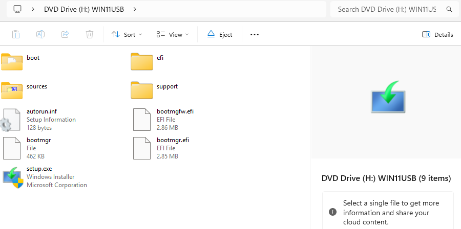
Next, mount your downloaded ISO in File Explorer by right-clicking it and choosing Mount. In response, Windows assigns it a drive letter automatically (I’ll use D:\ here, though it shows as H:\ in the lead-in screencap). Then open an elevated command prompt and use DISM to split install.wim into 3,500 MB chunks, small enough to fit safely inside FAT32’s 4GB per-file limit (if you cut’n’paste the following, it should be a one-liner at the command line):

dism /Split-Image /ImageFile:D:\sources\install.wim
/SWMFile:C:\X12Media\sources\install.swm ^      /FileSize:3500

DISM writes install.swm, install2.swm, and any additional parts directly into your target sources folder. Windows Setup picks them up automatically at install time — no extra configuration required.

Step 3 — Build the ISO Source Folder with Robocopy

Then, use Robocopy to mirror nearly all files from the mounted ISO into a clean working folder — but explicitly exclude the oversized install.wim you’ve already replaced with the split .swm files:

robocopy D:\ C:\X12Media\ /E /XF install.wim

The split .swm files you created in Step 2 are already sitting in C:\X12Media\sources\, so the result is a complete, well-formed ISO source tree ready for imaging. Everything Setup expects is present and correctly sized.

Step 4 — Generate Bootable ISO with oscdimg

Next, you need a copy of the MS Operating System CD Imaging utility, aka oscdimg.exe. You may need to install the Windows ADK (Assessment and Deployment Kit) from Microsoft if you haven’t already (oscdimg.exe ships with it). I found one inside the MiniTool Partition Wizard (MTPW), and used that version instead (worked like a charm). Wherever you get it, oscdimg.exe is the right tool for stamping a proper dual-purpose ISO. The command below targets both legacy BIOS (etfsboot.com) and UEFI (efisys.bin) boot sectors in a single pass:

oscdimg -m -o -u2 -udfver102 ^   -bootdata:2#p0,e,bC:\X12Media\boot\etfsboot.com ^   #pEF,e,bC:\X12Media\efi\microsoft\boot\efisys.bin ^   C:\X12Media C:\Output\Win11_X12.iso

The -m flag overrides the 4 GB maximum image size limit, while -u2 enables the UDF file system for broad compatibility. The resulting Win11_X12.iso in C:\Output\ is your custom X12 Hybrid boot media image.

Step 5 — Write Bootable USB Media with Rufus

Finally, download Rufus from rufus.ie and launch it as administrator. For the drive, I needed a native USB-C flash drive — I ordered a Kingston DataTraveler 70. Do not reach for a USB-A to USB-C adapter: the X12 Hybrid will not boot from one, full stop.

Select the Kingston DataTraveler 70 in Rufus, point the “Boot selection” field to Win11_X12.iso, and set the partition scheme to GPT with target system UEFI (non CSM), leaving the file system at FAT32. Rufus handles the split .swm files correctly because they are already embedded and sized within the ISO — no special Rufus settings needed. Click START, accept any warnings about erasing the drive, and within a few minutes you have fully functional X12 Hybrid boot media ready to go.

The Proof’s In the Booting…

I was relieved when the X12 finally booted from the Kingston UFD entry in the UEFI boot menu. That had been a LONG time coming. Even so, the extra steps described above add perhaps 15 minutes to a typical USB media build. That said, they reliably eliminate the frustrating “Windows cannot install required files” errors that plague direct installs on picky devices. Give this workflow a try on your X12 Hybrid — or on any device where you run into issues booting from USB media— and let me know how it goes in the comments below.

I’m glad to have the X12 back on the working roster. Indeed, I’m getting ready to upgrade it to a Beta Channel build shortly, Hopefully, I won’t need the repair/recovery media I just built. But if I do, I’ve got it handy. Here in Windows-World “better safe than sorry” are words to live by!

Facebooklinkedin
Facebooklinkedin

MCIO Ups the Ante on OCuLink

For most of computing history, the connectors with the fastest, most reliable PCIe signal paths lived in rack servers. They did not sit on your desk inside a palm-sized box. That divide is eroding quickly. MCIO, short for Mini Cool Edge IO, is a connector standard that Amphenol Communications Solutions developed. Better yet, the PCI-SIG formally adopted it for PCIe CopprLink internal cabling. Standardized as SFF-TA-1016, it packs PCIe Gen 5 performance, and soon Gen 7, into a slim 0.60 mm-pitch form factor. Until recently, you would only find it in a data center. In 2026, it is showing up in mini PCs you can buy on Indiegogo, as I learned reading news at TechPowerUp this morning.

How MCIO Ups the Ante on OCuLink

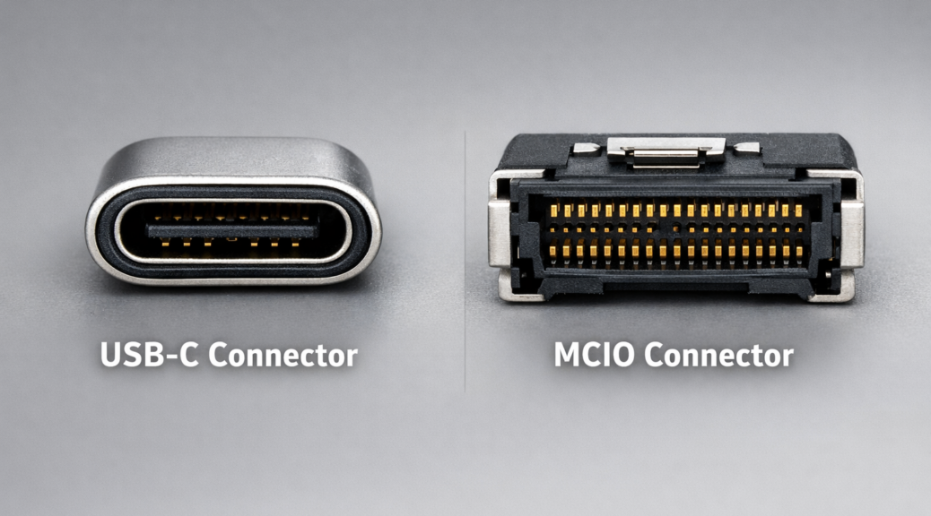
You can see how the MCIO receptacle compares with USB-C, which Thunderbolt 4/5 and USB 2/3/4/5 use. It’s a little bigger but not much. Indeed, MCIO deserves a closer look. It is a next-generation internal interconnect under the OverPass platform. Its defining characteristic is density without compromise. The connector’s 0.60 mm pitch keeps it compact while supporting data rates from 16 Gbps up to 64 Gbps per lane at PCIe Gen 5. Developers are also working on PCIe Gen 7 variants that run at 128 GT/s using PAM4.

Lane configurations span 4x, 8x, 16x, and 20x. The same connector body handles both cable-to-card and card-edge applications. That versatility reduces BOM complexity. It also supports PCIe, NVMe, and SAS, and the connector is rated for cable runs up to one meter. Designers originally created it to enable modular, scalable, easy-to-service data center architectures. As it turns out, those same traits also fit compact, high-performance personal computing.

Bandwidth Showdown: MCIO vs. the Field

To appreciate what MCIO brings to the table, it helps to line it up against the standards it competes against (and leapfrogs). Thunderbolt 4 tops out at 40 Gbps total bandwidth. But it tunnels PCIe thru an Intel controller, adding overhead at every step.

USB4 v2.0 is where things get faster: up to 80 Gbps, or asymmetric 120 Gbps when video bandwidth gets priority. It is the current mainstream performance sweet spot, and it appears in more mini PCs and laptops. Thunderbolt 5 pushes the ceiling higher, delivering roughly 63 Gbps of effective compute bandwidth, or up to 120 Gbps asymmetric for display workloads, with PAM-3 signaling. In real-world eGPU tests, Try Some Tech measured roughly 5.6-5.8 GB/s of host-to-device throughput.

OCuLink is an enthusiast’s current favorite for eGPU use (see my June 8 post on this topic). It’s a native PCIe external connection that sidesteps tunneling overhead entirely. In the same real-world testing, OCuLink hit roughly 6.6 GB/s host-to-device—beating Thunderbolt 5 by approximately 16% in sustained throughput. USB6 is still on the horizon as of mid-2026, not yet officially released, with predictions pointing toward roughly 160 Gbps using PAM-4 modulation.

Then there’s MCIO 8i running PCIe 5.0 x8: approximately 256 Gbps bidirectional at PCIe 4.0 speeds, and up to 512 Gbps bidirectional at full PCIe 5.0. That’s not an incremental improvement over the competition: it’s a category jump. GPD’s G2 eGPU enclosure, which launched in 2026 using MCIO 8i, claims just 2% performance loss when running an RTX 4090 externally. No Thunderbolt or OCuLink setup has come close to that. OCuLink typically imposes a 4–25% performance penalty depending on the workload; Thunderbolt 5 can push past 25% in bandwidth-intensive scenarios.

Data Center Roots, Professional Credibility

MCIO didn’t earn its reputation in hobbyist labs. It earned it in RAID controllers, host bus adapters, JBOD enclosures, NVMe storage arrays, AI inference servers, and high-density compute racks. In those environments, signal integrity and sustained throughput are vital. PCI-SIG adopted MCIO in its CopprLink cable spec in 2021, and Amphenol announced the PCIe Gen 7 variant for CopprLink internal cabling in 2025. It targets AI inference clusters and next-generation high-bandwidth networking.

Molex also manufactures MCIO connectors under the Mini Cool Edge brand, and the pricing reflects the standard’s enterprise practicality: raw surface-mount 8x PCIe Gen 5 connectors can be found for around $2.41 per unit, while a pre-assembled 16x cable assembly runs closer to $66. In enterprise bill-of-materials terms, that’s modest. For context, a Thunderbolt 5 controller chip alone can cost more than an entire MCIO cable assembly—one reason system designers are increasingly drawn to MCIO for cost-sensitive high-performance designs.

MCIO Shows Up in Mini PCs and eGPUs

GPD is best known for its gaming handhelds. But it made a significant statement in April 2026 by announcing two MCIO-equipped products at the same time. First came the GPD BOX mini PC, powered by Intel’s Core Ultra 300 “Panther Lake” processors. Second came the GPD G2 eGPU enclosure. The G2 launched on Indiegogo at $385 early-backer pricing ($459 MSRP) and is designed to pair directly with the GPD BOX over MCIO 8i. Beyond the headline MCIO port, the G2 is a capable dock in its own right. It includes a 16-pin GPU power connector (12VHPWR), an M.2 storage slot, USB 3.2 ports, dual connectivity via USB4 v2.0, and 100W USB Power Delivery output.

TOPC, another Chinese mini PC maker, also entered the MCIO space in 2026 with the TA255—an AMD Ryzen 7 H 255-powered system priced at approximately $394 (16 GB) to $438 (24 GB). The TA255’s MCIO port runs at PCIe 4.0 x8, delivering 128 Gbps—double the bandwidth of a standard OCuLink PCIe 4.0 x4 connection. That said, its current CPU generation stops it from reaching full PCIe 5.0 speeds.

One important caveat worth calling out: unlike OCuLink or Thunderbolt, MCIO is not hot-swappable and was not designed for casual cable-swap scenarios. It requires a deliberate, secure connection. For users building a modular compact workstation or eGPU setup intended to stay put, that’s a perfectly acceptable tradeoff. For users who want to plug and unplug an external GPU the way they’d swap a USB drive, MCIO is not the it—at least, not yet.

Should You Care About MCIO?

Let’s be honest: MCIO isn’t mainstream. As of mid-2026, device support is limited to a handful of mini PCs and eGPU docks. Most of them are Chinese OEMs with uncertain global reach. If you need broad compatibility today, USB4 v2.0 remains a safe, widely supported choice. If you own a capable mini PC or handheld and want the best eGPU performance, OCuLink is a good choice.

But if you’re thinking a few years out—or building a compact computing setup around modular, high-performance components—MCIO deserves serious consideration. PCI-SIG’s formal adoption of MCIO in its CopprLink cable spec for PCIe Gen 7 signals real institutional backing. It’s not just a niche vendor experiment. I expect to see MCIO appear in more PCs, edge boxes, and workstations in 2026/2027 as the ecosystem matures.

In connector technology, the server rack and the desktop have always eventually converged. On that trail, MCIO looks like the next proving ground. Stay tuned: this story is moving faster than most. Ultimately, it should mean that external NVMes work and run the same as internal NVMes. That’s HUGE.

Facebooklinkedin
Facebooklinkedin

USB Ports Need More Storage Bandwidth

In reading over Computex coverage I’m impressed by an array of newer, faster computing platforms and storage technologies. At the same time I’m depressed that USB-attached storage is not swimming in this rising tide of increased performance and capability. Simply put: USB ports need more storage bandwidth so they can hold up their end while ushering in a brave new world of performance computing. Let me explain…

Why USB Ports Need More Storage Bandwidth

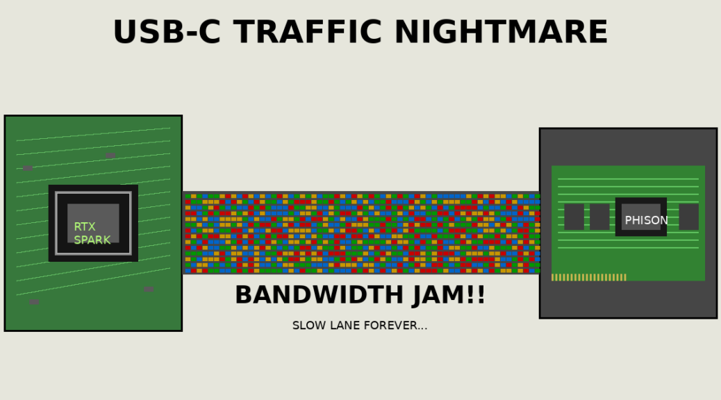
Thunderbolt 4 tops out at 40 Gbps — that’s a theoretical ceiling of roughly 5 GB/s, and real-world storage transfers run well below that. It was impressive when it arrived. It isn’t anymore. Thunderbolt 5 moved the needle, pushing up to 120 Gbps on the read side and 40 Gbps on writes. Indeed, its asymmetric bandwidth design delivers somewhere in the neighborhood of 6–7 GB/s of actual storage throughput under optimal conditions.

That’s a real boost, and to give credit where it’s due: Intel’s Thunderbolt 5 is the current high-water mark for USB-attached external storage performance. But here’s the problem — “high-water mark for external” and “keeping pace with internal” are two very different things. Alas, the gap between them is widening fast.

Phison’s PCIe 5 Controllers: Lapping the Field

Let’s talk about what’s happening inside the box right now. Phison’s E26 controller — the flagship PCIe 5.0 x4 part — pushes sequential reads up to roughly 14 GB/s and writes near 12 GB/s. That’s not a roadmap promise. That’s shipping silicon, today, in drives like the Crucial T705 and Seagate FireCuda 540. And the reason those numbers are possible is that PCIe 5.0 x4 delivers approximately 32 GB/s of raw bus bandwidth — a figure Thunderbolt 5’s best-case scenario can’t remotely approach.

I’ll be blunt: Thunderbolt 5 running at its theoretical maximum is still less than a quarter of PCIe 5’s available bus bandwidth. External storage users are working with a narrow pipe while internal NVMe users are drinking from a fire hose. And here’s what makes it even more galling — PCIe 5 SSDs themselves are already hitting their ceiling and looking nervously at what comes next. The interface they’re starved for is PCIe 6, which is already coming down the pipe.

Phison PCIe 6 Controllers: Next Tier Is Here

Computex 2025 was where Phison first made the PCIe 6.0 future feel real, and the momentum has only built from there. The next-generation Phison controller roadmap targets PCIe 6.0 x4 — an interface that theoretically delivers around 64 GB/s of raw bandwidth per slot, thanks to PAM4 signaling running at 64 GT/s per lane. Real-world sequential read targets are north of 20 GB/s.

Think about what that means for Thunderbolt 5’s ceiling. A single PCIe 6 SSD — one drive, one M.2 slot — could in principle saturate nearly five simultaneous Thunderbolt 5 connections running flat out. The Thunderbolt bandwidth ceiling doesn’t just look inadequate at that point; it looks comical. External storage users are so far behind that “catching up” is a massive understatement. Instead, designs must condider a completely different approach.

What Needs to Change?

USB4 Gen 3×2 sits at 40 Gbps — identical to Thunderbolt 4, still not enough. USB4 v2 bumps that to 80 Gbps, which helps at the margins but still lands less than a third of PCIe 5’s bus bandwidth, let alone PCIe 6’s. These are incremental improvements on an interface that needs a fundamental rethink, not a spec bump.

The industry needs a paradigm shift. Either Thunderbolt 6 or USB5 — whatever we end up calling it — must arrive with dramatically higher bandwidth, we’re talking 200+ Gbps as a floor, not a ceiling. Alternatively, PCIe tunneling over external cables needs to mature to the point where it can fully exploit NVMe speeds without  overhead that kills performance today. One or the other. Probably both, eventually.

Until one of those paths becomes real and shipping, external storage users are locked in a performance ghetto. Internal SSD buyers are sprinting ahead with every product generation. The storage industry owes external storage users a credible, substantive answer. I’m not talking about another incremental spec revision, not another narrowly defined workaround. Computex 2026 is the right venue and this is the right moment. USB silicon designers need to envision, then deliver something worth getting excited about. So far, I can’t see it. Let’s hope for something amazing, shall we?

Facebooklinkedin
Facebooklinkedin

ASUS Snapdragon Shows Odd Boot Anomaly

Here is a puzzle that took me longer than I care to admit to fully unpack. I built a recovery USB — clean DISM export, proper bootloader, everything by the book — set it first in the UEFI boot order, and rebooted an ASUS A14 Zenbook expecting to land in a familiar Windows Recovery Environment. Instead, I got the ASUS recovery stub. Every single time. I moved the USB higher in the boot order. I tried the firmware boot menu. I watched the machine apparently select the USB and then, silently and without apology, drop me into ASUS’s own mini-recovery UI anyway. The drive was not defective. The boot order was correct. The machine just did not care. This is my reason for saying: ASUS Snapdragon shows odd boot anomaly.

Getting Past ASUS Snapdragon Shows Odd Boot Anomaly

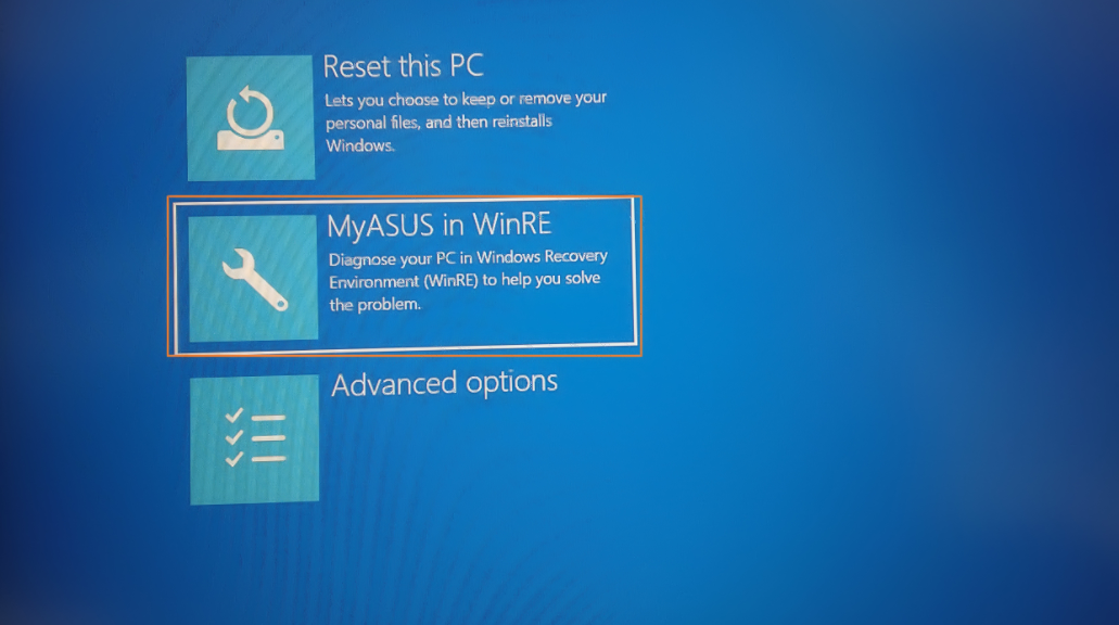
What I kept landing in was not Microsoft’s WinRE. It was ASUS’s recovery stub from firmware. It’s a minimal launcher, typically just a few hundred megabytes, that presents three or four tiles: Reset this PC, ASUS Recovery, and Advanced options. It looks vaguely like WinRE. It shares some ancestry with winre.wim. But it is ASUS’s gatekeeper, not Microsoft’s recovery environment, and it exists specifically to intercept the boot process before you can get anywhere else.

Here is the mechanism. ASUS, like most Tier-1 OEMs, configures its UEFI firmware with a hardcoded recovery boot path that fires during the BDS (Boot Device Selection) phase. It hits before the standard UEFI boot manager even looks at the user’s boot order. The firmware scans the internal NVMe for a partition stamped with a specific GPT partition type GUID — not the ordinary Microsoft Basic Data GUID, but a dedicated Recovery GUID or a custom OEM namespace. When it finds that partition, it hands control to the stub immediately. Your carefully ordered boot menu is consulted afterward, if at all. The USB was never really in the running.

Secure Boot adds a second layer of obstruction. Let’s say your hand-built USB carries an unsigned or self-signed bootloader (common with DISM-assembled media not signed against Microsoft’s KEK). Then,  the firmware rejects it silently and falls through to the next trusted entry in its internal list. That entry is the ASUS stub. So even when the BDS phase does get as far as examining external media, an unsigned USB is invisible. The machine looks like it’s ignoring you. It is, technically, but for a specific cryptographic reason (yes, really).

The WIM Recompression Tax

Once you understand why your DIY USB is being locked out, it helps to understand what the OEM actually ships in its place. It also explains why making a genuine ASUS recovery drive takes the better part of an hour. It starts with WIM compression. Microsoft’s stock winre.wim uses LZX compression and typically lands somewhere between 500 MB and 1 GB on disk. Manageable. Sensible. But ASUS’s customised image, once you add the recovery launcher, platform drivers, UI payloads, and potentially a full factory image, can balloon to several gigabytes of uncompressed data before anyone has touched the compression knob.

When you kick off the “Create ASUS Recovery Drive” process in MyASUS, what actually happens under the hood is a DISM /Export-Image /Compress:max operation (or its functional equivalent)  applied to an enormous source WIM. Maximum LZX compression, and on newer builds you may even see solid-block LZMS compression, which squeezes harder but runs even slower.

Here’s the critical detail: WIM compression in DISM is largely single-threaded. It reads every file, applies the compression algorithm, writes the output, and verifies integrity as it goes, all on one logical core (yes, really). On an otherwise fast NVMe-equipped laptop, that process still takes 40 to 55 minutes, not because the machine is slow, but because the algorithm is doing an enormous amount of intense, serialised work. The hardware isn’t at fault; the workload is.

Getting to USB-Based (Alternate) Boot

Here’s where the rubber meets the road. Getting external media to boot on an ASUS machine requires working around the firmware, not just the boot order. There are two reliable paths. First: disable Secure Boot in UEFI setup (DEL at POST, not F8 — more on that distinction in a moment). With Secure Boot off, unsigned bootloaders no longer get silently rejected. Second: on older platforms with CSM support, enabling CSM forces a legacy BIOS boot path that bypasses the UEFI BDS handoff to the stub.

The Bottom Line: Build Custom Recovery Media

Whether you use the MS supplied “Create a recovery drive” facility, or turn to the MyASUS toolbox to do likewise, the best way to protect an ASUS Zenbook A14 is to build recovery media from that PC. As I learned through a series of failed recovery attempts with other, supposedly generic, all-purpose recovery media, that stuff doesn’t fly inside the Zenbook’s firmware envelope.

Learn from my mistake, and follow this advice as soon as  you can. Otherwise, you too, will fumble around until you find the MyASUS in WinRE tool that does cloud-based image reconstruction instead. If all you want is WinRE running a command prompt, that’s not a good alternative. Do it now: don’t delay!

The Secure Boot Perspective (2 Days Later)

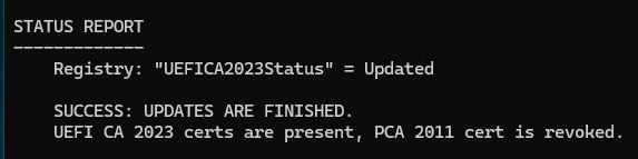
I just ran the Garlin scripts on the recently rebuilt ASUS Zenbook A14. Looks like one benefit of a constantly updated cloud-based restore is the ability to slipstream new stuff in (or replace older, outdated images with newer, current ones). The concluding status report from  that check script is pretty telling:Shoot! They’ve even revoked the CA-2011 certificate. Good stuff!!!

Facebooklinkedin
Facebooklinkedin

Making Boot/Recovery Media CA-2023 Compliant

OK, I confess. I’m more than a little OCD in keeping my Windows PCs updated. That applies to Secure Boot as much as anything else. And recently, in bringing my mini-fleet here at Chez Tittel up to snuff, I’ve found myself with old boot UFDs and current PCs. Yesterday, I blogged about that in a post about  “Checking Boot/Recovery Media…” Today, in reading the ElevenForum threads I learned that Garlin’s check script now includes boot media status. I also learned how to make my dozen or so bootable UFDs current.

Bootloader Is Key: Making Boot/Recovery Media CA-2023 Compliant

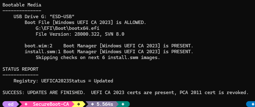
As you can see in the lead-in graphic the file named bootx64.efi is key to compliance. If the file is signed with CA-2023, it’s good; if it’s signed with CA-2011; it’s banned. Fortunately replacing a banned file with the good version is pretty straightforward. But because Windows doesn’t keep the C:\Windows\Boot\efi folder synched to what’s actually in the EFI partition, boot files are best garnered from the latter, not the former.

The steps in the process to provide a CA-2023 signed bootx64.efi therefore go best as follows:
1. Mount the EFI partition as an accessible drive: mountvol /S S:
2. Rename the existing UFD file to .old:
rename g:\efi\boot\bootx64.efi bootx64.old
3. Copy the CA-2023 bootloader into place:
copy S:\efi\boot\bootx64.efi to G:\efi\boot\bootx64.efi
4. Unmount the EFI partition for cleanup:

Note: On Macrium Reflect rescue disks you want to copy the CA-2023 version of bootx64.efi onto bootmgfw.efi instead.

Check Your Work: Run Garlin Script

You can use the latest version (be sure to download before use) of the Garlin Check_UEFI-CA2023.ps1 script to check your work. The correct syntax for this invocation reads (be sure to Unblock in advance):

.\check_UEFI-CA2023.ps1 -bootmedia -verbose

If all goes well the output should (nearly) match what you see in the lead-in graphic. If status shows BANNED, not ALLOWED, then the bootloader is signed with CA-2011, not CA-2023.

It’s pretty easy to fix, though. Hopefully you can do what I just did and bring all of your boot media into compliance. Cheers!

Facebooklinkedin
Facebooklinkedin

Stuck Inside Boot Alert Kills Whole Day

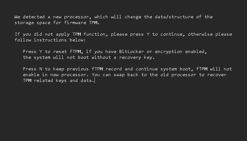
I mounted a full-throttle attempt to fix my “new CPU detected” boot warning, and lost a day to wandering in the wilderness. You’ve seen this screenshot before, in my February 27 post. I saw it a LOT more yesterday through at least 15 cold boots, plus various changes. Indeed getting stuck inside boot alert kills whole day, as I try to put my flaky startup situation right.

Why Stuck Inside Boot Alert Kills Whole Day

I’ll admit it: it was my own damn fault. I had to turn TPM off to attempt the warning breakout, but mistakenly also turned Secure Boot off as well. Big mistake. I’m *STILL* trying to recover from the latter, though I’ve managed to fix the former.

Along the way what wasted hour after hour was the impact of trying to boot in a half-open, half-closed Secure Boot environment. I kept getting stuck at Post Code 00 (nothing happened), Post Code 22 (graphics won’t initialize). I had to pop the CMOS battery out twice yesterday to reset the runtime to recognize all the hardware. Once I even had to disconnect all USB, network, and display peripherals.

A Trying Day Here at Chez Tittel

Chasing my tail is not always my idea of fun. Chasing the same trail of gotchas and glitches I’ve chased at least twice before is downright discouraging. But today, the machine booted (with the alert warning shown) and I’m up and running. I’m going to try one more time to get into UEFI, turn on Secure Boot (my only remaining hurdle to seal things back up) and see what happens.

Wish me luck. I’m going to need it. Here in Windows-World, there may not be enough time to do it right, but there’s always plenty of time to do things over and over … and over again until we get them fixed. Stay tuned: I’ll keep you posted.

Facebooklinkedin
Facebooklinkedin

Thunderbolt 5: Video Good, Storage Bad

I finally laid hands on a Thunderbolt 5 NVMe enclosure this week. I shouldn’t have bothered, though I learned something important. Aping Alex Karras’s unforgettable character Mongo in Blazing Saddles, I have to say that for Thunderbolt 5: “Video Good, Storage Bad!” Let me explain.

Why Say for Thunderbolt 5: Video Good, Storage Bad

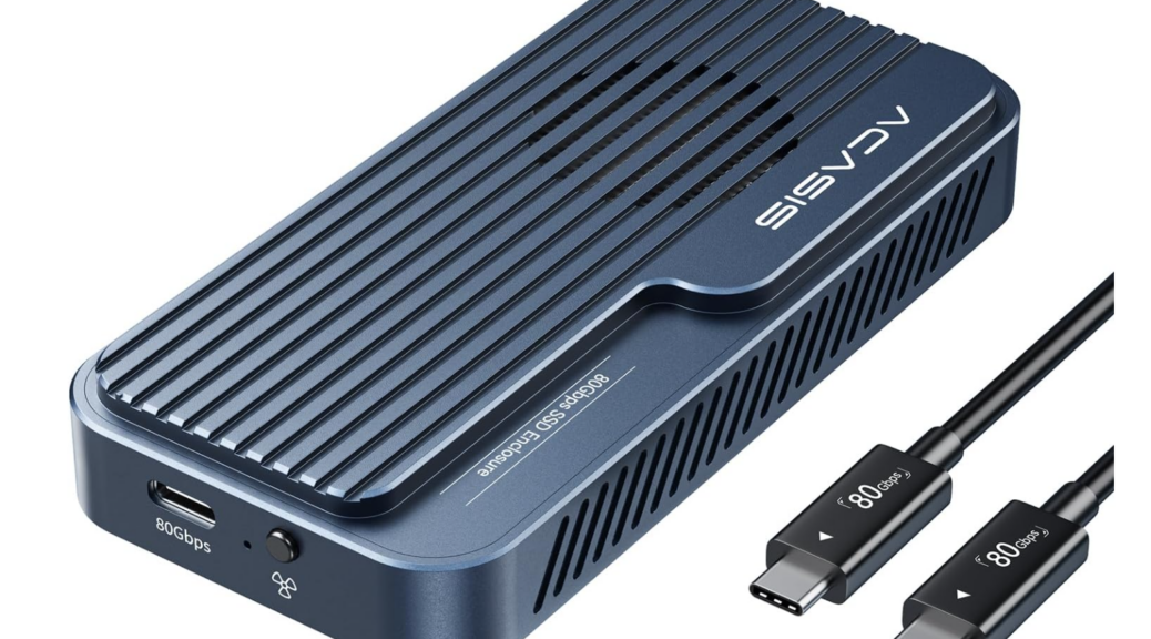
TLDR version: the channel is fast, but PCIe tunneling bandwidth peaks out at PCI 3.0 x4 levels. I tested a blazing fast Crucial T705 NVMe inside a brand-new Acasis TB501Pro NVMe enclosure (it cost me US$200+tax). It underperformed both the Samsung 970 EVO and the Crucial P3 NVMes I also tried out in that same box.

How can this be? Easy: The current TB5 controller generation from Intel — code name Barlow Ridge — includes a PCIe endpoint block that handles storage transfers to/from the TB5 USB-C port on the PC side of the connection. It’s hard-wired as PCIe 3.0 x4, which limits effective bandwidth for the link to somewhere around 3-4 GBps. Thus, there’s no real advantage in this generation of hardware in buying a TB5 NVMe enclosure.

Indeed, performance from a TB5 NVMe enclosure with a Barlow Ridge controller is the same as the USB-C port on my otherwise mind-blowing ThinkPad P16 Gen 3 laptop (which uses the same controller for TB5/USB4.0 v2). This isn’t going to get better until a next generation of controllers comes out, hopefully with a faster PCIe tunnel to boost NVMe access. This hardware doesn’t do what I wanted and hoped it would: offer 6-7 GBps speeds for external NVMe storage devices. That won’t change until Intel builds something faster for PCIe access.

In the meantime, save your money: you’ll get the same performance out of a TB4/USB4 NVMe enclosure as from this newer model, for around half the price. I’m sending mine back to Amazon, thankful for its “failed to live up to expectations” return policy. Sigh.


Facebooklinkedin
Facebooklinkedin

Sprucing Up My Desktop Peripherals

If you look back at my recent bloggage, you’ll see that I spent far too much time recently jumping into and rooting around in UEFI. Specifically, I found myself exposed to the oddities of the Asrock UEFI, which turns out to be finicky in many unexpected ways. Among many other bits of techno-trivia, I learned that my keyboard can’t send function key events to UEFI. I also learned that my logitech mouse sometimes is detected as (!) SATA storage during device enumeration at bootup. So, I’m sprucing up my desktop peripherals to steer clear of those issues. Let me explain…

Why I’m Sprucing Up My Desktop Peripherals

Function keys are helpful and even necessary during inital PC start for access to UEFI. They also drive many functions inside UEFI (e.g. F10 to “save & exit”). When the UEFI can’t read them, it’s anywhere from mildly annoying to maddening. My trusty old MS Comfort Curve 4000 (CC) is what’s known as a “composite USB HID device.” Alas, during POST and UEFI handoff, some PC firmware (including Asrock’s) handles only basic HID devices, not composite ones. To make that stuff work, in other words, I have to use a keyboard different from the CC. Sigh #1.

The older Logitech Unifying transceivers that work with mice and keyboards of that era also show another Asrock firmware quirk. They may sometimes (but not always) be recognized as SATA storage devices during first-time device enumeration. This threw me into an endless cycle of A6 POST errors on the B550 when I was trying to get the upstairs machine working last week. Here again, switching to a wired mouse fixed that issue. Sigh #2.

New Secure Boot, New Accoutrement

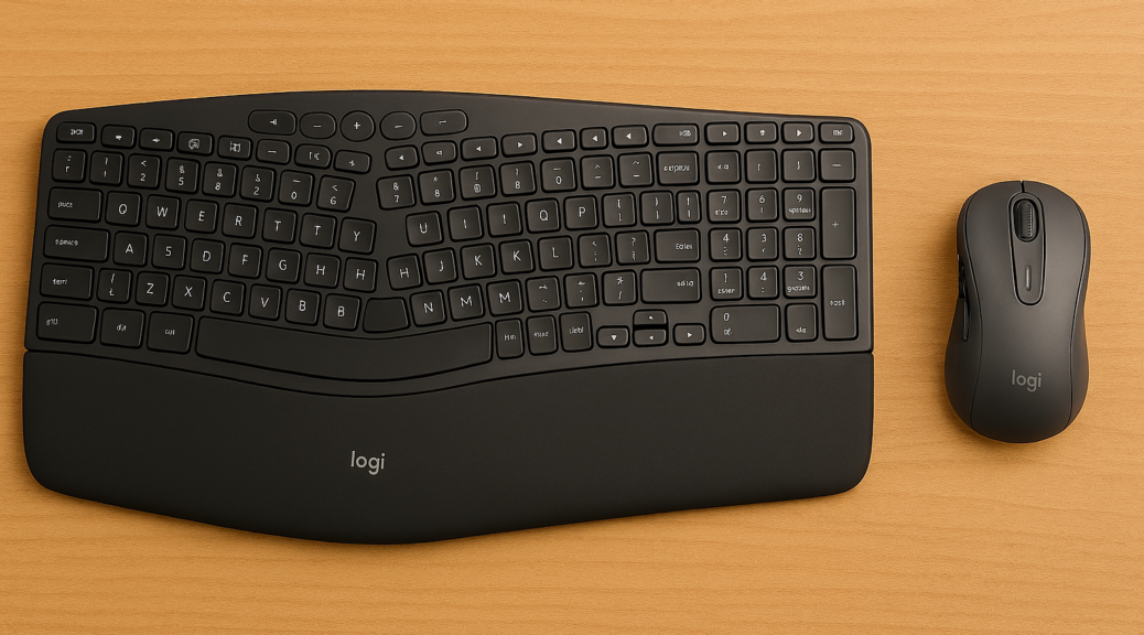
My fundamental problem is that I’m recycling old gear on a newer system. So it’s time to buy something new to bring it more in synch with the demands of modern UEFI, Secure Boot certificates, TPM 2.0 and suchlike. After walking thru my options with Copilot I’ve chosen a couple of Logitech items (I’m a long-time fan, and reviewed  lot of their peripherals in the 2000s for Tom’s Hardware):

  • Logitech Wavekeys keyboard (PN: YR0096) mostly matches the CC layout and feel, and is a basic HID device. Thus, its Fn keys should work properly in POST and UEFI.
  • In the same box, a Logi Bolt transceiver (xcvr PN: CU0021) which is supposedly superior to the old unifying xcvr, nor subject to mis-detection as a SATA device.
  • Logitech Signature M650 mouse (PN: MR0091) mostly matches the MS Mobile Mouse 4000 downstairs and the Logi mouse upstairs. Also works with Logi Bolt xcvr so I need only one transceiver for both devices.

I used the Bolt xcvr from the keyboard, so it came up instantly. I had to download and install the Logi Options+ app to get it to recognize the mouse through that same xcvr (it shipped with one of its own). But that was fast and easy, and the wireless link is quick and accurate. Alas, I got down on wireless keyboards back in the 2000s when I had a bad experience with transmission lag. If you type reasonably quickly (I’m at least 40 wpm or better) that’s not acceptable. So far, so good, with these Logitech devices.

Change is a watchword here in Windows-World. Like it or not (and I’m still figuring that out) my peripherals are changing. So are lots of others things. Adapt and thrive is the plan…

Facebooklinkedin
Facebooklinkedin

USB Type A Gen 1 vs 2 Tradeoffs

Laptop makers — like Lenovo, whose ThinkPad X13 Gen 6 I’m currently testing –must juggle many factors to build usable laptops. That includes managing cost, size, complexity and capability to hit specific price points. For this particular laptop, I’m currently pondering USB Type A Gen 1 vs 2 tradeoffs. The X13 includes 2 USB-C ports at 40 Gbps (with both USB4 and Thunderbolt 4 support). It also includes a single 5 Gbps (Gen 1) USB-A port as well.

Observing USB Type A Gen 1 vs 2 Tradeoffs

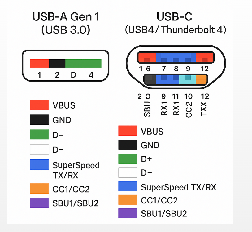
It’s pretty clear that USB-C ports cost more than their USB-A counterparts. The lead-in graphic shows that comes as a function of more leads and corresponding pin-outs. When comparing Gen 1 to Gen 2 for the same USB-A port, the cost differential is lower. Indeed, Copilot suggests it’s in the US$2.50 to 5.00 range per port.

Given such a relatively small difference I was interested to observe the performance difference between USB-A and USB-C. I used a fast UFD on the X13. I’m talking about the Kingston Data Traveler Max. It delivers full UASP speeds (up to ~1Gbps) if connected to USB-A Gen 2 or USB-C ports (10 Gbps or higher). The Kingston device includes a male USB-A port.  I was able to hook into USB-C thanks to a USB A-to-C adapter I purchased from Amazon  (current price ~US$4).

Comparing USB-A Gen 1 to Gen 2 Speeds

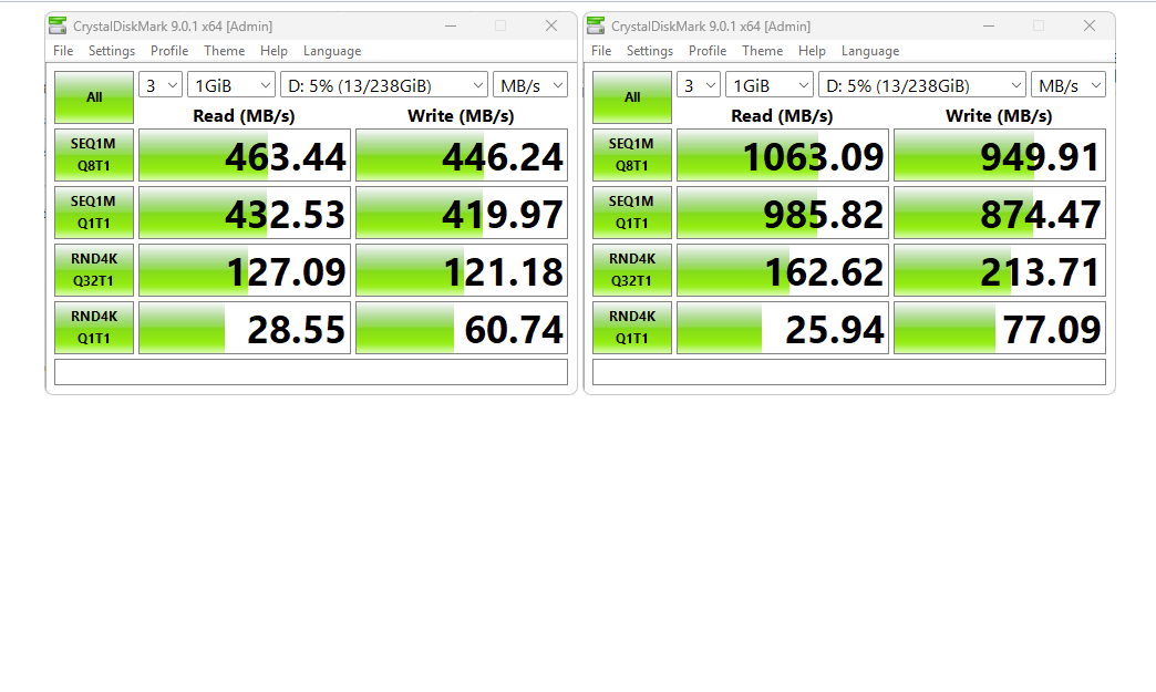
You can see the speed difference courtesy of CrystalDiskMark in the following dual screencap:

The USB-C hookup (right) is two times faster for the bulk transfers (top two rows), and random reads/writes (bottom two rows) run somewhat faster, too. Clearly, I’d rather have Lenovo use faster USB-A ports, if possible, and plug the Kingston Data Traveler straight in, instead of using an adapter.

But gosh, that’s the only way to get the best performance from that device, given the speed difference between the two ports involved. If you like, you could look at this as confirmation that a Thunderbolt 4 or USB4 dock for this laptop may indeed make a worthwhile accessory.  FWIW, Copilot reports the average price for such a device at “between US$210 and US$300” citing to devices from Startech, Walmart, Acasis and Dell as examples. It’s a hefty premium, but definitely delivers more (and faster) ports.

Choosing Gen 1 vs Gen 2

As I look at other Lenovo laptops here at Chez Tittel, I see the company often chooses Gen 1 ports for USB-A. The Snapdragon X T14S Gen 6 has two USB-A ports, both Gen 1 (Vintage: 2024). Ditto for the P16 Gen 1 Mobile Workstation (Vintage: 2022). OTOH, the P3 Ultra Gen 2 ThinkStation (not a laptop, but rather, an SFF PC) has 5 USB-A ports: all of them are Gen 2.

If I ran the zoo, I’d need a compelling reason to opt for slower Gen 1 over faster Gen 2 USB-A ports. I’m probably missing something important, because Lenovo still picks Gen 1 for many/most of its laptops. But murky mysteries are all part of the charm for those of us who labor in Windows-World. If I keep at it, maybe I’ll figure it out.

Facebooklinkedin
Facebooklinkedin

WTC = What the Clunk?

I bought my first hard disk back in the late 1980s. If memory serves it was a 300MB drive with 8″ platters. It cost about US$1,000. It attached via SCSI to a Macintosh SE desktop, with its 9″ CRT (512×342 resolution). Why tell you all this? Because that old drive was literally a clunker: as it started, or read data, or shut down it would emit a series of thunks and clunks you could hear in the next room. I just added a Seagate IronWolf 12TB NAS drive to my production desktop. This morning as I booted up I found myself saying WTC = What the Clunk? as it started up for the day.

Why I’m Saying WTC = What the Clunk?

I just looked up the innards of this new spinning disk. It’s got 8 platters, each with 2 heads and a total of 1.5GB of capacity. And  those heads and platters are sealed into a helium filled chamber to keep them as quiet as possible. Even so, spinning up apparently takes some mechanical oomph because I heard at least a trio of discernible clunks as the unit spun up this morning.

It had been so long since I’d heard those sounds, I’d forgotten what they sounded like. Now, I’m reminded of what I used to listen to all the time nearly 40 years ago: a steady series of thumps, clunks and thunks as big disks went about what — by today’s standards — can only be called “small business.” Fortunately, as the IronWolf goes about its much, much bigger business it only emits an occasional sound. If I use my imagination, I can hear it as a chuckle at the depth of my disk drive recollections.

I won’t even go back to the earlier days when I worked on Data General and DEC PDP minicomputers that used 14″ platters. Those came (and went) as removable disk packs. They made some industrial strength noise, for sure, in the days before Windows-World came along. But that’s a whole ‘nother story…

Facebooklinkedin
Facebooklinkedin